What Is Brush Tolerance Specification?
A brush tolerance specification should be judged by the actual job conditions, not by the product name alone. Start with access, residue type, surface sensitivity, brush stiffness, operating environment, and replacement routine. The right brush reaches the area, removes the target soil or finish defect, and avoids creating a second problem such as scratching, shedding, jamming, static risk, or contamination.
A brush tolerance specification is the set of permissible limits on key dimensions—such as overall diameter, core bore size, trim height, or mounting hole pattern—that a brush assembly must meet to interface correctly with the equipment. Unlike machined metal parts, brushes combine rigid hubs, backings, or cores with flexible filaments, so the tolerance logic is different: a tight bore tolerance may be critical for shaft fit, while a loose trim height tolerance may be acceptable if the brush is spring-loaded or used for non-contact sealing. The goal is to specify just enough control to support function without driving unnecessary manufacturing cost.
Which Brush Dimensions Commonly Need Tolerances?
Not every dimension requires a formal tolerance. The ones that matter most are those that affect how the brush mounts, rotates, or interfaces with a mating surface. Typical dimensions that may need tolerances include:
- Outside Diameter (OD) – critical for roller brushes that must fit into a housing or maintain a specific working gap.
- Core Inside Diameter (ID) / Bore – essential for shaft-mounted or keyed assemblies; slip-fit, press-fit, or clearance requirements drive the tolerance.
- Brush Length / Face Width – important when the brush must cover a specific cleaning or sealing zone without interference.
- Trim Height / Filament Free Length – affects contact pressure and wear; tighter tolerances may be needed when the brush is not spring-loaded or self-adjusting.
- Channel Width – for strip brushes inserted into a holder; too wide and insertion is impossible, too narrow and the brush rattles.
- Shaft Fit (Keyway, Set Screw Flat, or Bore Tolerance) – directly determines torque transfer and concentricity.
- Mounting Hole Patterns – for flange-mounted brushes; positional tolerance ensures bolt holes align with the machine.
- Concentricity / Runout – for rotating brushes at higher speeds, even small eccentricities can cause vibration.
Always ask: what does this dimension touch? If it locates, seals, or drives, it likely needs a tolerance. If it is free air or simply cosmetic, it may not.
How Tolerances Affect Fit, Cost, and Production
Tighter tolerances require more precise manufacturing methods—grinding, balancing, CNC machining, or post-molding inspection—which increase both unit cost and production schedule. Loose tolerances can be held with standard trimming, drilling, or extrusion processes, reducing cost but possibly sacrificing fit consistency. The tolerance specification also determines how parts are inspected: a ±0.010 inch bore may be checked with a simple go/no-go gauge, while a ±0.001 inch runout may demand a CMM or dial indicator setup, adding inspection cost and possible sample approval delays. Understanding your brush supplier’s typical process capabilities helps you specify tolerances that are both functional and manufacturable without over-engineering.
Types of Brush Assemblies and Typical Tolerance Considerations
Different brush constructions have different tolerance-sensitive features. The table below outlines common brush types and what to watch when specifying dimensions.
| Brush Type | Key Toleranced Features | Typical Fit Challenges | Notes |
|---|---|---|---|
| Roller Brush (custom or strip-wound) | OD, bore ID, face length, runout | Shaft fit inaccuracies cause wobble; OD variation changes cleaning gap | Balance may be required above certain speeds; specify service RPM |
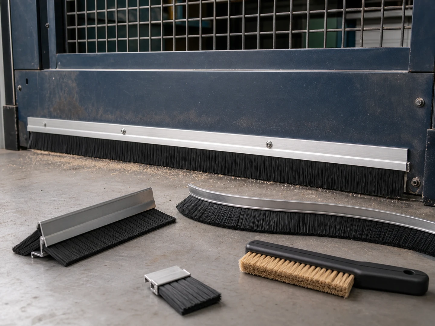
| Strip / Channel Brush | Channel width, back height, brush length | Oversized channel won’t slide into holder; undersized channel falls out | Use standard holder dimensions from supplier catalog if available |
| Cylindrical Cup Brush | ID, OD, trim height, wire diameter uniformity | Poor ID tolerance causes slipping on arbor; uneven trim height leads to uneven work | Often used on portable tools; arbor interface tolerance is critical |
| Tube / Flue Brush | OD, twisted‑in‑wire stem length, end ferrule | Too large OD won’t enter tube; too small OD provides insufficient cleaning | Flexible shafts may require length tolerance to avoid bottoming out |
| Wheel Brush | Arbor hole, face width, hub thickness | Bore tolerance determines arbor fit; face width must match mounting shoulder | Fill density and trim may also affect performance; not purely dimensional |
How to Specify Tolerances: A Practical Approach
- Identify functional interfaces. List every location where the brush touches the machine, tool, or workpiece. For each interface, note whether it locates, seals, drives, or simply clears.
- Determine the required fit type. Decide if the interface needs a sliding fit, press fit, running clearance, or a specific gap. For example, a bore for a shaft may need a clearance fit (e.g., +0.002/+0.006 inch) while a channel width may need an interference fit range.
- Consult supplier capabilities early. Ask your brush manufacturer what tolerances they can hold in standard production and at what cost. Some dimensions may require secondary operations (grinding, balancing) if specified too tightly.
- Prioritize dimensions. Only put formal tolerances on drawings for the few dimensions that directly affect function. Mark other dimensions as reference if needed.
- Use GD&T where helpful. For positional tolerances (mounting holes) or circular runout, geometric dimensioning and tolerancing symbols can convey requirements more clearly than linear plus/minus numbers alone.
- Request a first article inspection report (FAIR) for critical tolerances. This allows you to verify that the supplier’s interpretation matches your design intent before production runs.
Common Mistakes in Brush Tolerance Specification
- Over-specifying non-critical dimensions. Placing tight tolerances on filament OD or brush length when the brush is spring-loaded or the housing has generous clearance adds cost with no performance benefit.
- Under-specifying mounting interfaces. Ignoring bore tolerance, keyway size, or hole pattern location is a leading cause of brushes that don’t fit, vibrate excessively, or spin on the shaft.
- Copying metal part tolerances directly. A ±0.001 inch bore tolerance that works for a machined steel hub may be unattainable in a plastic or molded core without secondary operations.
- Forgetting environmental effects. Humidity and temperature can swell plastic cores or change filament stiffness, altering effective OD or trim height. Tolerances should account for the operating environment.
- Neglecting runout or balance for rotating brushes. A brush that runs true at 100 RPM may vibrate destructively at 3,000 RPM if no runout or balance requirement is on the print.
- Assuming all brush types can meet the same precision. A strip brush extruded into a flexible holder cannot hold the same OD tolerance as a machined cylinder brush; specify tolerances relative to the manufacturing method.
When Tolerance Specification Isn’t Enough
Dimensional tolerances alone cannot solve every brush performance problem. In these situations, additional requirements or an alternative approach may be needed:
- High-speed operation: Above roughly 5,000 RPM, even a dimensionally accurate brush may vibrate if not dynamically balanced. Specify a balance grade (e.g., G6.3 per ISO 21940‑11) and provide the service speed to the supplier.
- Precision grinding or finishing applications: When the brush must produce a specific surface finish or remove a precise amount of material, filament type, density, and trim uniformity may matter more than static dimensions. A trial run and sample approval is often more effective than over-tightening tolerances.
- Safety-critical assemblies: Brushes used in food processing, medical devices, or explosive atmospheres may require material certifications, design for cleanability, or compliance with industry standards. Tolerance specification is only one part of the qualification package.
- Custom fixturing or complex shaft interfaces: A brush that must clamp into a bespoke holder with multiple locating features may need a fixture design review rather than a simple plus/minus dimension list.
- Supplier capability limitations: If your required tolerances are beyond what the brush manufacturer’s standard processes can achieve, you may need to source a supplier with secondary machining capabilities or redesign the interface to be more forgiving.
Final Takeaway
Effective brush tolerance specification starts with understanding the functional interfaces, not by applying blanket precision to every dimension. Identify which dimensions truly guide, locate, seal, or drive, specify tolerances that the manufacturing process can realistically hold, and use first article inspection to confirm fit and function. By balancing engineering needs with process capability, you avoid unnecessary cost and lead-time while ensuring the brush does its job reliably.
Frequently Asked Questions
What is the difference between a brush tolerance and a brush specification?
A brush specification describes the overall requirements—dimensions, materials, filament type, density, and performance criteria—while a tolerance is the allowable variation for a particular dimension within that specification. For example, a specification might call for a 4‑inch OD; the tolerance defines how much that actual OD may deviate (e.g., ±0.030 inch).
Can I use standard machine shop tolerances for brushes?
Not always. Brushes combine rigid components with flexible filaments, so the same ±0.005 inch tolerance you apply to a metal bushing may be impractical and costly for a plastic core or a filament OD. Always check what the supplier’s production process can achieve without secondary operations.
How do I specify tolerances for a custom roller brush?
Start by defining the shaft diameter and the desired fit (e.g., slip fit with 0.002–0.004 inch clearance). Specify the bore ID tolerance, overall length, and OD. If the brush will spin at speed, add a runout or balance requirement. A simple assembly drawing with the critical dimensions boxed in and tolerances noted is often sufficient.
What happens if I don’t specify any tolerances?
The supplier will use their own standard manufacturing tolerances, which may be looser than your application requires. This can lead to brushes that don’t fit the shaft, bind in the housing, or fail prematurely. Without stated tolerances, you also have limited recourse if the parts vary from your expectations.
How are brush tolerances measured in production?
Common inspection tools include go/no-go gauges for bores and channels, calipers or micrometers for lengths and trim heights, dial indicators for runout, and coordinate measuring machines (CMM) for complex hole patterns. The measurement method should match the tolerance—a ±0.001 inch dimension may need a CMM, while a ±0.030 inch dimension can be checked with a simple gauge.
Should I specify a tolerance for the filament trim height?
It depends on the application. If the brush is spring-loaded or the working gap is large, a trim height tolerance of ±0.060 inch or more may be fine. For precision brushing where the brush tip must contact a surface consistently, a tighter trim tolerance (e.g., ±0.015 inch) may be necessary, but consult your supplier because tighter trim tolerances can significantly increase manufacturing cost.
What GD&T symbols are most useful for brush drawings?
For positional tolerance of mounting holes, the true position symbol is common. For rotating brushes, circular runout or total runout can control wobble. Flatness or parallelism may apply to mounting flanges. Use GD&T when it communicates the functional requirement more clearly than linear plus/minus tolerances—but keep it simple to avoid over-complicating the drawing.
How does sample approval fit into tolerance specification?
Prior to full production, request a pre-production sample (also called a golden sample) measured against your tolerance requirements. This allows you to verify that the supplier’s interpretation of the drawing leads to a brush that actually fits and functions in your machine. After approval, the measured sample dimensions become the reference for ongoing quality control.
Technical References
When are Strip Seal Brushes the wrong choice?
- Strip Seal Brushes — Use rubber lips, foam, labyrinth seals, air curtains, or rigid scrapers when pressure sealing or liquid containment is required.
- Wheel Brushes — Use a cup brush for broad open surfaces, an end brush for confined recesses, or a non-brush process when the target finish or surface cannot tolerate rotating filament contact.
- Cup Brushes — Use a wheel brush for a narrow edge or profile, an end brush for a confined recess, or a non-brush method when the surface cannot tolerate rotating filament contact.
- Roller and Conveyor Brushes — Use a stationary strip brush for a fixed linear seal or wipe, or another process when rotating line contact interferes with the product or cannot discharge the residue safely.
What should replace Strip Seal Brushes when they stop working?
- Strip Seal Brushes — Strip brushes create a linear barrier or guide; machine-table brush plates distribute load and support products over a broad area. Closest alternative: Machine Table Brush Plates.
- Wheel Brushes — Wheel brushes give narrow edge contact; cup brushes cover a broader open face, while end brushes concentrate contact at the end of a small stem for recesses.
- Cup Brushes — Cup brushes cover a broader face than wheel brushes; end brushes are better for small recesses or pockets where the cup body blocks access.
- Roller and Conveyor Brushes — Roller and conveyor brushes hold cylindrical line contact across a working width, including helix-wound builds where the filament path is set to move loosened material toward one side; a strip brush holds the same line without rotating, so it seals or wipes but cannot carry residue along the width.